![Radioddity GD-168 [OPEN BOX] - Radioddity](http://de.radioddity.com/cdn/shop/files/GD-168_1600x1600_3922a234-2fe4-4b80-8282-3f6d17a10d71.png?v=1741052607)


![Baofeng GT-5R 5W Dual Band Radio [Upgraded Legal Version of UV-5R] - Radioddity](http://de.radioddity.com/cdn/shop/products/GT-5RImage.png?v=1616751303)
![Baofeng UV-5R PLUS [5 Colors] | DUAL BAND | 4/1W | 128CH | FLASHLIGHT - Radioddity](http://de.radioddity.com/cdn/shop/products/3_58c037e1-560a-4c85-bd75-67c202269d29.jpg?v=1620894599)


![GA-2S UHF Long Range USB Two way Radio [2/4/6 Packs] - Radioddity](http://de.radioddity.com/cdn/shop/products/5_96d2d28c-8609-4f29-926b-d423141df2f4.jpg?v=1598864722)


![Baofeng BF-888S [2 Pack] | UHF | 5W | 16CH | CTCSS/DCS | Flashlight - Radioddity](http://de.radioddity.com/cdn/shop/products/1___1___1.jpg?v=1609202373)
![Baofeng GT-1 [2 Pack] | UHF | 5W | 16CH | Flashlight | FM Function Two-Way Radio - Radioddity](http://de.radioddity.com/cdn/shop/products/ia_100000006122.jpg?v=1610525724)


Xiegu VG4 Review | First Impressions, Tuning Notes, and Initial Experience
- Ham Talk, Product Review
-
 Posted by Jackson Chen
- Leave a comment
--- by Eric N Balles, W1ENB
Introduction
I have recently reengaged in the amateur radio hobby after a long hiatus. My primary technical focus is currently on practical and efficient antennae. Like most everything in life, antenna design, configuration, mounting, orientation, etc., are a compromise involving numerous variables. Most of my experience to date has been with simple wire antenna and I have enjoyed reasonably good performance even near the solar cycle minimum (e.g., Boston to Ukraine voice contacts using a 40 m EFHW at 5 watts). My interest in exploring vertical antennae and specifically the
Xiegu VG4 was to evaluate (qualitatively for now) potential benefits and tradeoffs between antenna types – with verticals, for example, having a low take-off angle and radiating uniformly in the azimuthal direction versus the higher take-off angle and radiation nulls that horizontal center fed dipoles and EFHWs exhibit. The VG4 covered the four bands of most interest to me, and I was especially interested in its 40 m capability.
Initial Impression
• All items received, nothing missing, neatly packed
• Counterpoise and capacitor hat radials as well as build hardware appear to be stainless (e.g., band clamps are all labeled 304 SS)
• Machined components nicely done, chamfered holes, etc.
• Matching transformer box has a thick gasket and weep hole
• Traps have a well-formed elastomeric seal at the top and generous weep openings at the bottom; trap orientation is clearly labeled
• Total weight of the antenna components (measured on an electronic balance) was 5.1 kg
• Supplied tools are a nice touch – especially the L-shaped wrench for tightening the band clamps


Antenna assembly went very smoothly. The supplied instructions were sufficient but perhaps could benefit from additional information. I made my own initial choice on tube-to-tube insertion lengths (see below in Initial Build section) and I received a quick response and an excellent photo from customer service to confirm the intended connection point for the braid coming off the matching transformer box (see photo). I understand that Radioddity and/or Xiegu are developing enhanced documentation for the VG4.


Antenna Measurement Configurations
My planned final installation was atop a 6.1 meter steel mast anchored below ground level and attached to the facia at the roof peak of a detached garage. Since I expected to be making numerous adjustments and measurements prior to and after final installation, I made measurements either:
• [A] with the antenna mounted to a test fixture in a vertical orientation which had the counterpoise radials at approx. 2 meters above ground level; or
• [B] with the antenna in a horizontal orientation across non-metallic supports that were approx. 2 meters above ground level (note: I removed the two counterpoise radials closest to the ground to minimize coupling effects); or
• [C] with the antenna in the final location atop the steel mast with counterpoise radials at approximately 6 meters above ground level (and 2 meters above the roof peak).
Antenna characteristics were measured primarily using a NanoVNA-H, calibrated using a short-open-load-through routine, and data captured using NanoVNA Saver (0.3.10) software. The sweeps were configured using 10 segments which provided 1000 data points per sweep. I also used an ICOM 7300 SWR graph feature to cross check the NanoVNA results at the final configuration and installation. All listed frequencies and VSWR measurements are from the NanoVNA unless otherwise noted.
Initial Build
I decided to make my initial build with the radiating elements in their longest configuration to establish what the lowest resonant frequencies could be. To that end, I chose a 3 cm insertion length at each tube junction (approximately the length of the cut in each of the larger tube ends). The only exception was the tube sections between the 10 m and 15 m traps which came preassembled with the traps and I chose to leave that dimension as supplied. I pre-measured and marked lengths on each tube to help keep track of future adjustments. Ultimately, since I operate mostly SSB, I planned to optimize the VG4 configuration for the lower frequencies of the voice portions of each band.
The initial build mounted in a vertical orientation on the test fixture [A] yielded the following resonant frequencies and SWR values in the four bands:
Initial Build / Measurement Configuration [A]
| Band | Resonant Frequency (ƒ(r)) | VSWR @ ƒ(r) |
| 10 meter | ƒ(r) = 27.8 MHz | 1.3 |
| 15 meter | ƒ(r) = 27.8 MHz | 1.05 |
| 20 meter | ƒ(r) = 14.0 MHz | 1.05 |
| 40 meter | ƒ(r) = 6.9 MHz | 1.4 |
10 Meter Band Adjustments
The 10 meter band radiating elements were easily accessible with a ladder so I was able to make adjustments and measurements while the antenna remained vertically mounted to the test fixture. I made three adjustments from the initial build length and observed the corresponding shifts in resonant frequencies.
10 Meter Band Adjustments / Measurement Configuration [A]
| Band | Initial build | -3 cm | -6 cm | -9 cm |
| 10 meter | ƒ(r) = 27.8 MHz | ƒ(r) = 28.2 MHz | ƒ(r) = 28.5 MHz | ƒ(r) = 28.7 MHz |
| 15 meter | ƒ(r) = 21.2 MHz | ƒ(r) = 21.2 MHz | ƒ(r) = 21.25 MHz | ƒ(r) = 21.27 MHz |
| 20 meter | ƒ(r) = 14.0 MHz | ƒ(r) = 14.02 MHz | ƒ(r) = 14.02 MHz | ƒ(r) = 14.04 MHz |
| 40 meter | ƒ(r) = 6.9 MHz | ƒ(r) = 6.9 MHz | ƒ(r) = 6.9 MHz | ƒ(r) = 6.9 MHz |
Of note is that the adjustments at this point showed a measurable shift in the 10 meter band resonant frequency with a modest change in radiating element length. At this configuration, a 9 cm reduction in length yielded a 900 kHz shift, or about 100 kHz increase in resonant frequency per centimeter reduction in section length ( -100 kHz/cm). I observed little to no change in resonant frequency for the lower bands with the 15 meter band shifting only about -8 kHz/cm.
Relationship Between Close-to-Ground Vertical and Horizontal Orientations
I dismounted the antenna from the test fixture and laid it horizontally across supports (antenna measurement configuration [B] described above). Due to the VG4’s overall length, adjustments to the lower bands needed to be done with the antenna closer to ground level. Also, I wanted to see what, if any, correlations could be made between measurements made in a horizontal orientation near ground, in a vertical orientation in a test fixture near ground, and the final installation at 6 meters above ground level. This information would potentially be useful to minimize the number of times the antenna would need to be raised and lowered from its intended final installation.
Comparison of Measurement Configurations [A] vs [B]
| Band | Configuration [A] | Configuration [B] |
| 10 meter | ƒ(r) = 28.7 MHz | ƒ(r) = 28.0 MHz |
| 15 meter | ƒ(r) = 21.27 MHz | ƒ(r) = 21.22 MHz |
| 20 meter | ƒ(r) = 14.04 MHz | ƒ(r) = 14.04 MHz |
| 40 meter | ƒ(r) = 6.9 MHz | ƒ(r) = 6.9 MHz |
At this point, it was encouraging to see a reasonable match of the resonant frequencies observed in the vertical and horizontal orientations albeit both close to ground. The thought is that one can take advantage of this by establishing the approximate relationship between length changes and corresponding resonant frequency shifts would facilitate easier initial band tunning. Resonant frequency shifts from close-to-ground orientations to final installation elevation will be discussed later.
15, 20 and 40 Meter Band Adjustments
At this point, the 15 meter resonant frequency was close to my target and, without knowing yet how it may shift at final elevation, I decided to leave that element length unchanged.
The 20 meter resonant frequency was significantly below my target so I ran through a set of length adjustments and corresponding resonant frequency measurements while the antenna was in the horizontal near ground measurement configuration [B].
20 Meter Band Adjustments at Measurement Configuration [B]
| Band | post 10 m adjust | -1.5 cm | -6 cm | -8 cm |
| 10 meter | ƒ(r) = 28.0 MHz | ƒ(r) = 28.0 MHz | ƒ(r) = 28.0 MHz | ƒ(r) = 28.0 MHz |
| 15 meter | ƒ(r) = 21.22 MHz | ƒ(r) = 21.22 MHz | ƒ(r) = 21.22 MHz | ƒ(r) = 21.2 MHz |
| 20 meter | ƒ(r) = 14.04 MHz | ƒ(r) = 14.063 MHz | ƒ(r) = 14.135 MHz | ƒ(r) = 14.16 MHz |
| 40 meter | ƒ(r) = 6.9 MHz | ƒ(r) = 6.9 MHz | ƒ(r) = 6.93 MHz | ƒ(r) = 6.93 MHz |
Of note, as stated by Xiegu, there is essentially no impact on the upper bands when making adjustments to lower bands – so 10 m and 15 m resonant frequencies were not affected. And for the range of 20 m radiating element length changes carried out here, there was only a small shift in the 40 m resonant frequency. Empirically, for 20 meter band tuning, measurements suggest a resonant frequency shift with section length changes of approximately -15 kHz/cm.
A similar exercise was carried out with the antenna in the horizontal near-ground measurement configuration [B] to determine the 40 meter band tuning guideline. Empirically, measurements suggest a resonant frequency shift with radiating element length change to be approximately 2.4 kHz/cm.
Relationship Between Close-to-Ground and At-Final-Elevation Measurement Configurations
At this point, I felt I had enough empirical information in hand for the close-to-ground configurations and was ready to raise the antenna to its final elevation. I made a final set of measurements in all three measurement configurations for the antenna as left from the most recent experiment above.
Comparison of Measurement Configurations [A] vs [B] vs [C]
| Band | Configuration [A] | Configuration [B] | Configuration [C] |
| 10 meter | ƒ(r) = 28.7 MHz | ƒ(r) = 28.0 MHz | ƒ(r) = 28.4 MHz |
| 15 meter | ƒ(r) = 21.18 MHz | ƒ(r) = 21.05 MHz | ƒ(r) = 21.27 MHz |
| 20 meter | ƒ(r) = 14.09 MHz | ƒ(r) = 14.18 MHz | ƒ(r) = 14.35 MHz |
| 40 meter | ƒ(r) = 6.98 MHz | ƒ(r) = 7.10 MHz | ƒ(r) = 7.23 MHz |
The data suggests that the higher bands are affected more by ground coupling effects than the lower bands. It is very likely that the absolute value of the measured data reported above are specific to my measurement environment.
Fine Tuning and Characteristics at Final Elevation
At this point I am armed with resonant frequencies at the intended elevation and empirical estimates of the relationship between radiating element length changes and resonant frequency shifts. For the 10 and 15 meter bands, the resonant frequencies was at or very close to my target. In addition, the bandwidth is sufficiently broad (observed to be neat that specified by Xiegu) that no adjustment was warranted. However, the 20 and 40 meter band resonant frequencies were off a bit from my target and warranted adjustment – which of course meant the mast with antenna attached needed to come down and back up one more time (no small feat even with help from family members). I used the guidelines established above to make my adjustments (+8 cm on the 20 m band; +21 cm on the 40 m band).
Comparison of Measurements at Final Elevation
(before and after final adjustment)
| Band | 1st time at elevation | 2nd time at elevation |
| 10 meter | ƒ(r) = 28.4 MHz | ƒ(r) = 28.4 MHz |
| 15 meter | ƒ(r) = 21.27 MHz | ƒ(r) = 21.26 MHz |
| 20 meter | ƒ(r) = 14.35 MHz | ƒ(r) = 14.23 MHz |
| 40 meter | ƒ(r) = 7.23 MHz | ƒ(r) = 7.16 MHz |
The 20 meter band adjustment was spot on. The 40 meter band adjustment overshot my target slightly, by about 15 kHz. I made the easy decision that one more small tweak was not worth the substantial effort of bringing the mast + antenna down and then back up again!
Key antenna length measurements
(after the 2nd (final) adjustment)
| Band | Section Measurement Description | Length (cm) | Length (inches) |
| 10 meter | ƒ(r) = 28.7 MHz | 340.4 | 134 |
| 15 meter | ƒ(r) = 21.18 MHz | 24.1 | 9 1/2 |
| 20 meter | ƒ(r) = 14.09 MHz | 42.9 | 16 7/8 |
| 40 meter | ƒ(r) = 6.98 MHz | 181.3 | 71 3/8 |
Plots of SWR as a function of frequency from the NanoVNA covering the full range of the United States amateur 40, 20, 15 and 10 meter bands after final adjustment and at final elevation are shown below.

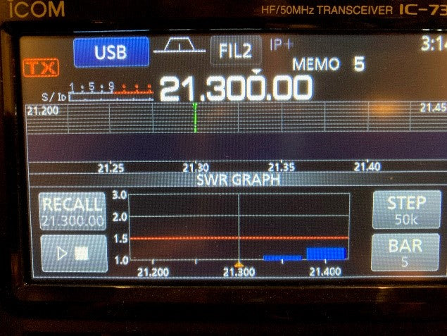
Screen shots from an IC-7300 show SWR as a function of frequency measured after final adjustment at final elevation for the portions of the 40, 20, 15, and 10 meter bands that are of particular interest for my intended use of the VG4 are shown below.


Resonant Frequency Shift in Wet Conditions
Resonant frequency shifts during wet conditions (rain and for some period after)
exhibited with antennae in general, and with vertical HF antennas using traps in
particular, are known to occur. I had the opportunity to measure the effects of
wet conditions on the VG4 shortly after a moderately heavy rain.
Comparison of Measurements Under Dry vs Wet conditions
(after final adjustment at Final Elevation)
| Band | Dry | Wet |
| 10 meter | ƒ(r) = 28.4 MHz | ƒ(r) = 27.94 MHz |
| 15 meter | ƒ(r) = 21.26 MHz | ƒ(r) = 20.77 MHz |
| 20 meter | ƒ(r) = 14.23 MHz | ƒ(r) = 13.96 MHz |
| 40 meter | ƒ(r) = 7.16 MHz | ƒ(r) = 7.04 MHz |
The resulting shifts in resonant frequency were not unexpected.
The magnitude of the frequency shift, coupled with the shape of the SWR curves,
suggests that tuner adjustments are almost certainly warranted on the 40 and 20
meter bands, probably also on the 15 meter band, and less so on the 10 meter
band.
As expected, the VG4 resonant frequencies returned to almost exactly the
previously measured values when conditions dried.
Discussion on various radio forums frequently point to moisture ingress to the
traps as the primary culprit for SWR shifts in vertical HF antennae. Others hold
the view that there are different, broader mechanisms at play (such as changing
ground moisture level, for example). In my opinion, the shifts that I observed
(shown above) are unlikely due to moisture ingress in the VG4 itself given the
new condition and the observed quality of the upper trap seals, the top
radiating element cap, and the matching transformer box seal.
Initial Performance on the Air
My experience on the air pleasantly matched my expectations. I was able to
quickly pick up a few new countries in the first few weeks (snapshot from my QRZ
log shown below – all at 100 W from 30 km northwest of Boston, MA). Of course,
this provides only a qualitative assessment of VG4 performance, and my other
benchmarks are primarily wire antennae. Quantitative comparisons between the VG4
and other antennae could be made using WSPR, for example, and may be one of my
future projects.

Summary and Final Thoughts
I found the VG4 to be of high-quality materials and components that were easily
assembled. Tuning was relatively straightforward as described by Xiegu. For my
benefit to simplify the tuning process (and possible for the benefit of others),
I found the approximate relationship between length adjustments and resonant
frequency shift for the following bands to be:
10 meter band: - 100 kHz / cm
20 meter band: - 15 kHz / cm
40 meter band: - 2.4 kHz / cm
When it comes to antenna height, it is generally thought higher is better. SWR
can certainly be influenced by distance from ground as well as other objects.
Xiegu’s recommendation of 3 meter minimum base elevation seems like a reasonable
height provided nearby structures are not significantly above that height. In my
case, garage and house structures would have distorted the radiation pattern at
that minimum elevation so I elected to mount the antenna with a base elevation
at 6 meters above grade (2 meters above the roof peak) and took advantage of the
building to support the mast. I did not feel the need to further stabilize the
antenna with guy wires. Xiegu has a published wind speed rating of 35 m/s
(approximately 80 mph). I watched the VG4 closely during a storm with 50 to 60
mph gusts and thought it was quite sturdy.
In my opinion, the VG4 is worthy of consideration from a couple of perspectives.
The price – performance point makes it a great choice for a first or single HF
antenna – a) multi-band (single coax run / no need for antenna switches); and b)
relatively small footprint (useful where a tower or long wires are not
practical). In my case, I was looking to install a multi-band antenna that also
covered 40 meters at a remote location on our property where a single coax run
was a major cost constrain. For me, it was a great choice.
73 de W1ENB
9 Kommentare
Patrick Giyan
KK7JXM, i’m having a terrible time tuning the same antenna you have, and I desperately need some help. Could you give me your measurements of the tubes? I have tried all kinds of measurements and nothing seems to work. I noticed you started off with a 3cm insertion on the tubes I take it. That would mean the top tubes also. I’m trying to get this antenna open in the air so I can use it. It would be a great help if you could tell me those measurements. I’m only concerned with the bottom tubes and the very top tubes. Thank you very much. I read you your review and it was good.
ON4VP
Reading this extensive report on this vertical antenna got my attention. I was looking for a Cuscraft R8 (I had one before and was pleased with it’s performance) or a Cushcraft R6000. The main reson are the use of warc bands which lacks on this 4-ban antenna. But price and construction seems ok and attrictive to me. Thanks for this FB report. 73 Phil
Jim W0JPO
Bugs have antennae
Hams have antennas
Good review, would only say that recording the 2:1 SWR as well as the f at the lowest swr would be helpful in quantifying the tradeoffs in optimizations that you did.
Seems like a good value, notwithstanding the construction issues that some reviewers noted. Presumably the vendor is responding appropriately.
Those nanovnas are really something aren’t they? Same for the tinySA spectrum analyzers. Serious tools that were previously out of reach for most of us.
73
Jim W0JPO
Bruce R Finley N3VET
I PURCHASE ONE AND IT HAS BEEN UP FOR A YEAR NOW, IT PERFORMS VERY WELL TUNES ALL BANDS WELL, I COMPARED THE RECIEVE TO MY g5RV WIRE ANTENNA , WORKS ABOUT THE SAME, WHAT I DID NOTICE LESS STATIC NOISE ON THE VERTICAL.
OVERALL IT IE A NICE CONSTRUTED ANTENNA , HOLDS UP WELL IN THE WIND . I USE IT ALL THE TIME ON 40 METERS ..
I WAS ABLE TO USE MY PALSTAR HF AUTO TO TUNE 80 METERS AND IT DID WELL ON THAT BAND ALSO ..
Jackson
Hi Harry S., I’ll let our customer service member contact you to provide help.