Your Cart

You are away from getting a FREE Raddy CL-1 Campaign Light!
CLICK HERE to learn details.

Congratulation! A FREE Raddy CL-1 Light will be shipped with your order automatically!
You're away from upgrading it to a FREE Radioddity HF-008 Antenna!
CLICK HERE to learn details.

Congratulation! A FREE Radioddity HF-008 Antenna will be shipped with your order automatically!
CLICK HERE to learn details.

€0,00

Radioddity Help Center

  • Radioddity

  • Baofeng

  • Xiegu

  • TYT

  • Accessories

  • Other Tips

  • Radio Comparison

GD-77
GD-77S
GM-30
GA-510
GA-2S
GD-73
GM Series
CB-27
FS-T1/PR-T1
RV6
R2
PAX100
DB25/QB25
GS-5B
DB20-G
DB25-D
DB25-G
Clear Active Client ID Library In GD-77
Firmware Update Failure
GD-77 Advanced Mode
GD-77 Blank Display
Privacy Key Length Is Shortened
Does GD-77 Support NXDN?
Encryption Capability Info GD-77
Clear Active Client ID Library In GD-77

There is no key combo to blank the contents of the Active Client ID Library.
The following procedure will achieve the same goal.

Open Active Client
Hold # key Side Key 2 and Menu while turning the radio on.
Read the radio to display the contents
Open the Data Dump file from the DMR ID folder
Open a Blank Excel file
Copy the top 2 lines from the Data Dump and paste into the Blank file
Edit the first entry to seven zeros for the Radio ID, change the Callsign, Name and Nickname to R4DIO, Test, and Entry
Save this new file in .csv format.
Close Active Client
Open Active Client
Import the .csv you just created
Close Active Client
Open Active Client
Read Radio to verify

This is a few extra steps, but will erase the entries and replace with one test entry.

Firmware Update Failure

For the firmware update error, please find the vcredist_x86_2008 file in the Firmware software V3.1.8--update software document and run it first. It is a database which can help you solve the error. Please see the screenshots below:

Firmware_Update_Failure-01.png

Firmware_Update_Failure-02.png

Firmware_Update_Failure-03.png

After you run the vcredist_x86_2008 file, please restart your computer, replug in the radio and try to update the firmware again.

If you prefer to use the vcredist_x86_2008 package in English, this is the same module that can be downloaded from Microsoft here:
https://www.microsoft.com/en-us/download/details.aspx?id=29

--- Choose English as the language
--- Download
--- substitute this file for the file that is in Chinese
--- Run as Administrator

If your computer pops out the error "Update.exe – System Error The program can’t start because STDFU.dll is missing from your computer. Try reinstalling the program to fix this problem."

The file "STDFU.dll" is already included in the original download folder. The solution is that the "Update.exe" program MUST always be in the exact same folder as the "STDFU.dll" file and cannot be moved.

GD-77 Advanced Mode

How to enter the advanced mode in the GD-77 programming software?

Press Ctrl+Alt+Shift+5, enter the password: DMR961510
or
Press Ctrl+Alt+Shift+F11, enter the password: DMR961510

GD-77 Blank Display

Solution:
Would you mind following the operation in the link below and see if the display problem can be fixed?
https://radioddity.s3.amazonaws.com/Radioddity - repair GD-77 white screen.pdf

If the display still shows nothing, please write back with your radio's serial number and we will help you further.

Privacy Key Length Is Shortened

Question:
Why in GD-77 firmware V3.1.9, the privacy key is shorter than V3.1.1?

Left: V3.1.1. Right: V3.1.9
Privacy_key_length_is_shortened-01.png

Answer:
64 bits actually does not work on the radio, so we cancel it in the new firmware.

Does GD-77 Support NXDN?

Question:
Does the RADIODDITY GD-77 support NXDN digital communication?

Answer:

No

Encryption Capability Info GD-77

Questions:
I would like detailed information on the encryption capabilities of the Radioddity GD-77 DMR radios please.

Answer:

Encryption protocol: ARC4

P.S.
Some customers may say they saw the GD-77 is equipped with an AES chip in some disassembly photos. The encryption chip of GD-77's vocoder library is AES, but for the radio encryption protocol, it only supports ARC4 for now.

GD-77S Firmware Update Instructions

Below are the steps necessary to update the Firmware in a GD-77S. The link is specific to the version available when these instructions were created and may need to be updated to reflect the latest version.

These steps will fill in some of the possible gaps in earlier documentation and make the First firmware Update a little less intimidating, or help refresh your memory if it has been a while since you have last updated your firmware.

GD-77S Firmware Update Instructions

1. If you haven't already, download this archive: https://gd-77.s3.amazonaws.com/GD-77S%20Firmware%20V1.3.0%20%26%20Software%20V1.1.10_20190712.zip

2. Extract the files from the archive

3. Open the Firmware Software Vx.x.x folder (x.x.x refers to the actual firmware version)

4. Open the Update Operation Word file in this folder

5. Review or print the Update instructions. Use these to fill in any gaps that are causing difficulty.

6. Turn Off your GD-77S and insert the Program Cable into the radio and USB Port.
A. On the side of your GD-77S are 2 extra buttons below the PTT button. These are referred to as Side Keys in the instructions.
B. Press and hold the Black Side Key 1 and the Blue Side Key 2.
C. Turn on the radio while still holding the Keys.
D. When the indicator is Green in color, this indicates that the radio has entered the Update mode.
E. Release the Side Keys,

7. Open the Update Software folder in the same folder as the Update Operation Word file.
A. Observe the folder starting with Eng. This contains the update Application, It is named Update.exe.
B. Open the folder starting with 'ENG followed by the version.
C. Right Click on the Update application . (Update.exe)
D. Choose Run as Administrator.
E. If you encounter a Windows pop-up asking permission to open the application, choose Yes.

8. Click on the Browse Button and select the Update file.
A. It will be in the Firmware Software folder referenced in step 3.
B. The Firmware file will be labeled GD-77S_Vx.x.x (x.x.x refers to the actual firmware version)
C. Choose the Firmware file by clicking on it.
D. Click on the Open button below and to the right.
E. The actual Firmware Update file is loaded into the Update application.
F. Click on the Download button (on right; second from the top)
G, The small Blue boxes in the center will show the progress
H. When the update file has been loaded a Status pop-up named Update with the message 'Update success' will open .
9. Click OK.

10. Turn the Radio Off
A. Close the Update application (Note: leave application open is you will be updating more than one radio and repeat steps 8 and 9 above for each.) When last radio is updated, proceed to step 11. .

11. Remove Program Cable from Computer and Radio
A. The firmware has now been updated

Firmware Update To Correct Tones And Bandwidth


If the radio is not allowing you to select bandwidth or set a tone from the menu, it will need to have the firmware updated to remove all preset tones and make that Menu selection active, as well as the Bandwidth options.

To update the firmware, use the following link:
https://radioddity.s3.amazonaws.com/Radioddity_GM-30_Firmware%2020210403%20%26%20Software_V2.06_20210430.zip

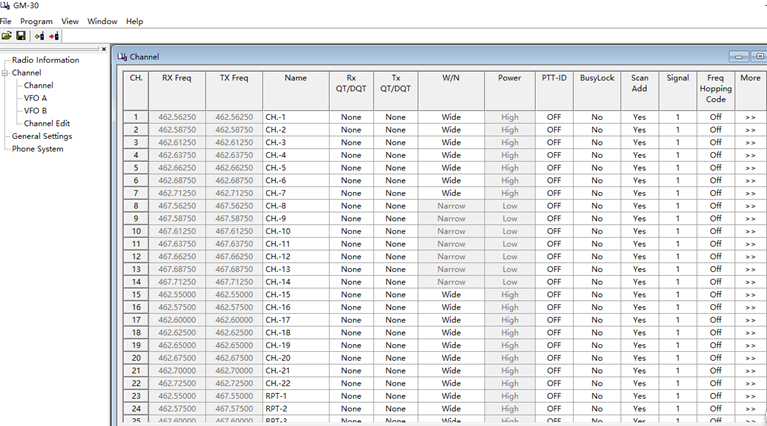
Download and Extract the files from the archive and open the GM-30 Programming Software folder


Open the Radioddity GM-30 v1.05 en installation app.


Install the Programming Software and Open App


Plug the programming cable into the computer
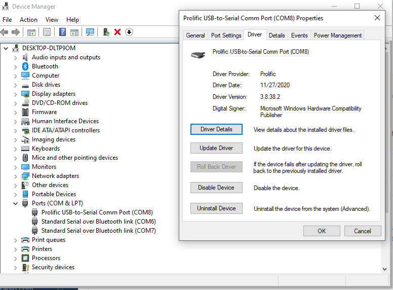
Open Device Manager to determine com port number


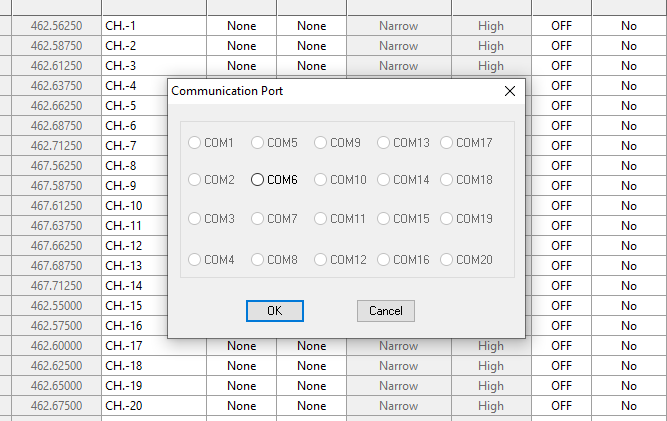
Select Communication Port from the Program Tab


Select the appropriate port


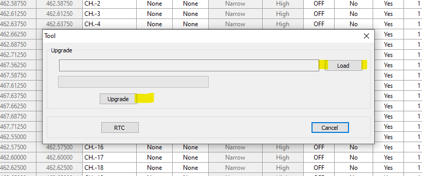
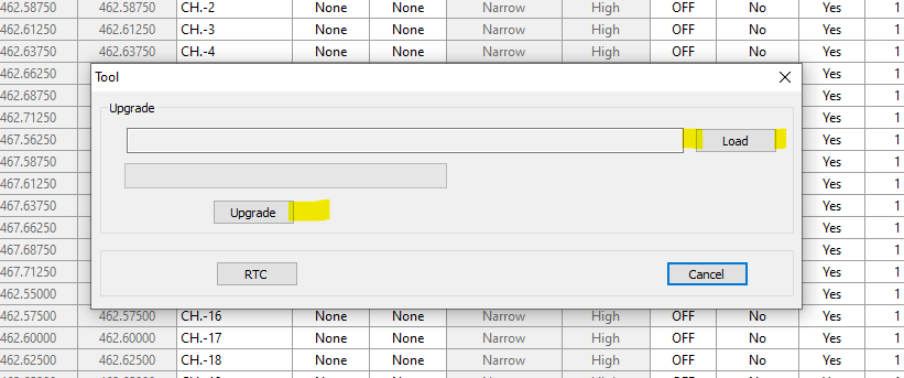
Select Program, then Tool


Select and Load the Upgrade file from the GM-30_Firmware Update folder


Plug the programming cable into the radio
Press and hold the PTT + LED key, then turn the radio on
Click Update - Wait for 100%


Turn the radio off, remove the programming cable
Turn the radio back on and select Menu Option 40 and follow through to Reset the radio.

The Bandwidth settings should now be corrected and existing DTDSS/SCS tones removed.
The CTCSS/DCS Tones can now be set from the programming software and written to the radio, or by using Menu Options 9 through 12

Menu Option 25 Memory

While the online Manual has the correct information, the manual that came with your radio may contain an error in the Menu Item description for Option 25 - Memory.

Menu Option 25 - Memory 000 - 127

The manual gives this description: This menu is used to delete the programmed information from the specified channel (0 through 127) so that it can be either programmed again or be left empty.

The correct description:
When saving a channel, this menu is used to save the programmed information for the specified channel (000 - 127). If a number is preceded by "CH-" the channel already has channel parameters stored.

We hope this clears up some confusion. Enjoy your GA-510, and don't hesitate to contact us if you need assistance.

Active The VOX For GA-2S
Can GA-2S Connect With Motorola CP200?
How To Scan On GA-2S?
Active The VOX For GA-2S

Question:
How to active the VOX function on the GA-2S/BF-888S/BF-88A/BF-88E?

Answer:
To enable the VOX function, here are two ways:

1. Select the current channel to one of the 1-5 channels, press and hold the PTT and Moni button to turn on the radio, then you will hear the voice prompt that the VOX is on. In this way, all the 16 channels have been activated the VOX function and the user can talk directly to transmit without pressing the PTT button. With the acoustic tube earpiece, the users can hear and talk more clearly.

2. You can activate the VOX function in the programming software. Select the VOX function and all the 16 channels can use the VOX function directly. Normally turn on the radio and you can use the VOX function no matter which channel you are at.

To turn off the VOX function, turn off the radio, set the current channel to one of the 1-5 channels, press and hold the PTT and Moni button to turn on the radio, then you will hear the voice prompt that the VOX is off. If the VOX is turned off, you will see the VOX function is not selected when you load the radio to the programming software.

Active_the_VOX_for_GA-2S.png

Can GA-2S Connect With Motorola CP200?

Question:
I was wondering if the radioddity GA-2S long range two way radio can connect with a cp200 Motorola if same frequency and channel.

Answer:
Yes, they can communicate with each other under analog mode with correct programming.

How To Scan On GA-2S?

Question:
How to scan multiple channels on a GA-2S radio? I can't seem to get the radio to scan like in the instruction manual. Pressing the monitor button only monitors that current channel (and usually gives me loud static sounds).

Answer:
There is no scan function on GA-2S.

Can't Install The Driver/Run The CPS On Win10
Can't Run The CPS [Missing libusb0.dll]
Setting Of Encryption, Message, Squelch
Can't Install The Driver/Run The CPS On Win10

Some GD-73 users reported that they can't get the driver installed well on Windows 10 or can't run the programming software on Windows 10. Below are two solutions to solve the problem:

Solution #1:
Install the driver as administrator

Solution #2:
If the driver still can't be installed correctly even if the user has run it as administrator, please suggest the user remove the original driver and then install the driver from the following link:
https://sourceforge.net/projects/libusb-win32/files/

Users can also find the download link for this driver by searching "libusb-win32-src-1.2.6.0.zip" on the internet. No need to install the original driver we provide if users have installed this driver.

Can't Run The CPS [Missing libusb0.dll]

PROBLEM:
Customer reports that he can't run the GD-73 programming software(CPS) on his computer. An error showed up and said that file libusb0.dll is missing.

Background--why the software of GD-73 is different from other radios:
The combination of charging and programming from the same connector has introduced the need for a new driver installation and installation order to be required. For the first time running the GD-73 CPS on a computer, the user needs to install the driver first and get the radio connected with the computer.

Solution:

1. Turn on the radio and plug in the programming cable (to both radio and computer).

2. Install the driver. Most important, run the driver installer application as Administrator to install the required driver.
For more information about installing the driver, please see the following instruction:
https://radioddity.s3.amazonaws.com/2019-06-05_Radioddity_GD-73_ Getting_On-Air_V1.0.pdf

3. Open Device Manager and look for a device named libusb-win32 devices. Open it and it should have a cable icon and walkie-talkie-C7000 beside it.

4. Now, with the radio connected to the computer and verified by the device in the Device Manager, you can run the CPS.

5. After the first time running the CPS, you can open it with or without connecting the radio on the same computer next time.

Setting Of Encryption, Message, Squelch

Questions:
The functions I would like to use on the GD-73E are the following:
-enter a code for the encryption
-enter a short message
-open the squelch to check if a frequency is free.

Answer:
*All these three functions can only be set on the CPS

-enter a code for the encryption:
Encryption1.png

-enter a short message:
To send short message on the radio, user needs to add quick text in the CPS first. And this can only be done on the CPS.
Encryption2.png

-open the squelch:
Set the squelch level in the General Settings.
Encryption3.png

Channels Not Written From CPS

When writing to the radio with the programming software, you may encounter blanks where some channels are not written, or an incomplete Write process. Here are some short rules to a Complete and Accurate Write process.

If CTCSS/DCS or CTCSS/DCX Are chosen from Channel information screen, and no tone is selected, it is shown as OFF

If CTCSS/DCS or CTCSS/DCX Are chosen from Channel Information Edit screen (Click the More option), and no tone is selected, it is shown as None

Tones must be chosen from the Channel Information screen to be able to write to radio.

Check the items below before starting the Write process:

--- If no tone is chosen, it needs to show OFF in the Channel Information screen.

--- If Decode/Encode tones show any combination of OFF and None on any channel, the Write process will not complete

--- If any tone shows None, it will not write to the radio, (the Write process will not complete).

--- It will not initiate the Write process if the screen is in Sleep Mode (not showing).

Error Code: (Abnormal reading and writing, check the connections are correct, or walkie-talkie power supply is turned on!)

We hope you enjoy your iRaddy GM series 3-IN-1 UHF Phone Case radio. Don't hesitate to contact us if further assistance is needed.

How To Set The CB-27 to AM Mode?
Does The CB Antenna Require A Ground Plane?
How To Set The CB-27 to AM Mode?

Problem:
How to set the CB-27 radio to the AM mode?

Answer:

Regular operation:

Long press [A/F] key to select AM mode and FM mode. However, such a change only possible if the set channel is also allowed in the respective operating mode. The respective operating mode is indicated on the LC display with "AM" or "FM" to the left of the channel number.

If the user is in UK and uses the UK norm frequencies, the UK norm only has FM mode. Press [A/F] key will only switch the radio to CE version. User need to switch the norm to EU first.

1. For changing the current norm, please hold [A/F] key while turning the radio on. The current
norm appears in the display.

2. Use the channel selectors [UP] and [DN] keys of the microphone to set a different norm
Confirm your selection by turning the radio off and on again.

*If the instruction above does not work, please ask the customer for the operation video to show the issue.

Does The CB Antenna Require A Ground Plane?

Question:
Will this require a ground plane? 28-715-009

Answer:
If you want to launch the signal out into the atmosphere to reach a further transmission range, we recommend that you get a ground plane.
If you have a fiberglass vehicle or boat, you don't require it. The coaxes shield is used for counterpoise (substitute for the ground connection).

What Are The Numbers Displayed On The Right Of The Frequency?

Question:
I recently purchased the FS-T1. What are the 25 50 75 numbers displayed on the right of the frequency? These are not documented. On the unit, the 50 is always showing on channels 1-14 (Tx or Rx), no numbers showing on channels 15-22, and I never see the numbers 25 and 75 displayed except on boot-up.

Answer:
The numbers are the accuracy of the frequency. Take the FRS frequency 462.5625 as an exanple, the radio only displays 462.562, as for the 0.0005, there will be a small number 50 on the right of the frequency, which means the accurate frequency is 462.562 50.

Battery Cover Is Difficult To Remove
Radio Freezes With All Static
Battery Cover Is Difficult To Remove

The Battery Cover on your Voyager RV6 Marine VHF Radio is highly water-resistant and a tight fit. The Belt Clip, if installed, will put pressure on the battery cover, making it more difficult to manage. For the first few times, remove the belt clip until you get accustomed to the process. Remove the antenna and have the radio face down with the top facing you. Place the radio on a towel or something soft that won't scratch the lens. With a slight downward pressure to start, pull the Battery Cover latch toward the top of the radio; which should be facing you, then lift slightly to see if it has completely released. When the latch has cleared the case, hinge the cover-up toward you. There will be resistance on the lid lifting because of the seal to keep water out and off of the battery. It is going to be a tight fit, and should remain that way - so the technique of releasing the latch and lifting that first-quarter inch will be the part that will take practice.

You can develop your own style. but when pulling latch toward you, you can stabilize the top of the radio with the other hand. This may make a more stable way of holding, rather than using the other hand to hold the radio. This procedure is just so you can work with it a few times until you feel comfortable holding the radio in one hand and opening the cover with the other.

We hope this will make the process a bit easier.

Radio Freezes With All Static

Problem:
The RV6 radio suddenly froze up with all static when listening to the whether station. Tried reboot the radio and reinstall the battery, but the radio froze again and the keyboard has no control.

Solution:
To avoid static and the radio froze up, please reinstall the battery, press and hold [VOL/SQL/MONI], and then turn on the radio to enter set mode.
Press [VOL/SQL/MONI] again to select "AL", then press DOWN Button to switch to "OF", power OFF.
Then press the POWER button to power ON again, it will back to normal.

Scan & Squelch Tail
Scan & Squelch Tail

Question:
1. Can I use scan on any channel? I use the lower channels and its a bit annoying to have to change to channel 16 when i want to scan.
2. I also noticed when the R2 is on channel 16 and i turn the R2 on, scan starts automatically and i can't turn scan off.
3. How to eliminate squelch tail when receiving transmission from different brand radios?

Answer:
1. Can I use scan on any channel? I use the lower channels and its a bit annoying to have to change to channel 16 when i want to scan.
-- No, the scan can only be turned on when the radio is turned to channel #16.
2. I also noticed when the R2 is on channel 16 and i turn the R2 on, scan starts automatically and i can't turn scan off.
-- If there are more than two channels are added into the scan list, channel #16 will only function for turning on the scan. Switch to other channels than #16 can turn off the scan.
3. How to eliminate squelch tail when receiving transmission from different brand radios?
-- It is normal to have squelch tail when receivig from different brand radios. There's no way to eliminate it because different brand has different squelch tail elimination way.

Can PAX100 Amplifier Work With Icom 705?

As long as the IC-705 can provide a low trigger on PTT and you are able to build a keying cable, it should work. The pin out of the cable would have to come from the Icom. The radio will have a data jack on the rear panel, and it will have Ground and PTT available to connect to the keying cable that comes with the radio.

Save Channels With Offset Without Using A Computer
Missing File Errors When Installing The CPS
Save Channels With Offset Without Using A Computer

It is difficult to save an offset to memory when programming the QB25 without a computer.

The following steps will allow you to save a complete channel with offsets and any signal tones necessary.
Delete channel (if necessary) - Menu 45
Switch to VFO
Enter RX Frequency (enter zeros if needed to fill all blanks. Example 146.7000)
Enter RX Tone (if needed)
Save to empty channel - Menu 44

Enter TX Frequency (enter zeros if needed to fill all blanks. Example 146.1000)
Enter TX Tone (if needed)
Save to the same channel as RX frequency - Menu 44
(Hold the Right knob in until it returns to the operating screen)
Change to Memory, Select Channel, and check operation.

Missing File Errors When Installing The CPS

When trying to open the DB25 or QB25 CPS, you may encounter an error that a file that is necessary for the program to run is missing.

Navigate to the folder where the application is located and right-click on the app: DB25QB25_VIP_CPS

Select Run as Administrator - Windows should now find the file that is in the same directory as the App and allow you to use CPS.

If the problem persists, the missing file(s) will have to be registered.

This is more likely to occur on a new computer where the Microsoft communications support files have not all been registered.

==================================

This is How Users can Fix the MSCOMCTL.OCX is Missing Error

1. Check the Desktop’s or Laptop’s System Details
2. Register the MSCOMCTL.OCX File on 64-bit Systems
3. Register the MSCOMCTL.OCX File on 32-bit Systems
4. Reinstall the Software

Check the Desktop’s or Laptop’s System Details
1. First, users should check whether their laptops or desktops are 32 or 64-bit systems as the directory users need to register the MSCOMCTL.OCX file for is not the same for both. To do so, press the Windows key + S hotkey.
2. Enter the keyword ‘system information’ in the search box.
3. Click System Information to open the window in the shot directly below.

DB25-1.png

4. Then select System Summary, and check the System Type detail there. An x64 system type is a 64-bit system.

2. Register the MSCOMCTL.OCX File on 64-bit Systems
Users with 64-bit desktops or laptops will need to register an MSCOMCTL.OCX file for the SysWOW 64-bit folder. To do so, open File Explorer with the Windows key + E hotkey. Then open this folder path in File Explorer: C:WindowsSysWOW64.

DB25-2.png

The SysWOW64 folder will need to include the MSCOMCTL.OCX file. If it doesn’t, users will need to get that MSCOMCTL file from an OCX file directory or by copying it from another PC. However, note that some website sources for OCX files might not be entirely reputable. Some users might find an MSCOMCTL.OCX file in a third-party software folder so tries searching for the file with Windows’ search utility first. When you’ve copied a valid MSCOMCTL.OCX file into the SysWOW64 folder, follow the guidelines below to register the file.


1. Press the Windows key + R hotkey.

2. Enter ‘cmd’ in Run, and press the Ctrl + Shift + Enter hotkey, which will open an elevated Command Prompt window.

3. Next, open the SysWOW64 folder by entering ‘cd C:WindowsSysWOW64’ in the Command Prompt’s window and press Return.


DB25-3.png


4. Then input ‘regsvr32 mscomctl.ocx’ in the Prompt, and press the Enter key.


DB25-4.png


3. Register the MSCOMCTL.OCX File on 32-bit Systems

Users with a 32-bit system will need to check that there’s an MSCOMCTL.OCX file in the cd C:WindowsSystem32 folder instead of SysWOW64. Copy an MSCOMCTL.OCX file into System32 if that folder doesn’t include the required file. In addition, 32-bit system users will need to enter cd C:WindowsSystem32 in an elevated Command Prompt. However, users can still register the file with the same ‘regsvr32 mscomctl.ocx’ command.


4. Reinstall the Software

Aside from registering the OCX file, users have also confirmed they’ve fixed the MSCOMCTL.OCX error by reinstalling the software that doesn’t run. That will ensure the software installs correctly. Users can reinstall the software in Windows as follows.

1. Open the Run window with the Windows key + R keyboard shortcut.

2. Input ‘appwiz.cpl’ in Run and click OK to open Windows’ uninstaller.


DB25-5.png


3. Select the software that the MSCOMCTL.OCX error arises for.

4. Select Uninstall or Uninstall/Change option.

5. Then click Yes to confirm.

6. Restart Windows before reinstalling the software.

7. Then reinstall the latest version of the software.

So, that’s how users can fix the MSCOMCTL.OCX error message in Windows to kick-start certain software. First, try reinstalling the software as that’s probably the more straightforward resolution.

GS-5B Transmit When Connected To The Computer
Compatibility Between Radio And Earpiece, Mic
GS-5B Turns Off The Bluetooth Connection At 98.7% Completion
GS-5B Transmit When Connected To The Computer

Please CLICH HERE to download the solution file.

Compatibility Between Radio And Earpiece, Mic

Question: I got some static from the earpiece, it does have a push to talk button and Mic and when you transmit the meter on the front of the radio shows it doesn't transmit as well. It's not very strong.

Answer: The mics that we are selling are currently not perfectly compatible with the GS-5B because it doesn't support DUAL PTT. Take the RS22 as an example, and the user could only transit via channel A or B.

GS-5B Turns Off The Bluetooth Connection At 98.7% Completion

Question: When attempting to upload/write from iPhone to the GS-5B via bluetootBluetoothBluetoothh, the radio turns off the bluetooth connection at 98.7% completion every time.

Answer: It does not go beyond 98.7% on a complete Bluetooth upload. I read the radio using the PC software after sending a Bluetooth upload ending at 98.7% and all channels were present. It only goes up to 77% on a complete read using the PC software. A Write process using the PC Software is complete at 77%. 77% of what, I do not know, but it reads and writes the entire contents (84 channels) showing Success at 77%. I do not think it is a hardware problem, but I am sorry for the inconvenience it caused.

Antenna Recommendation

We currently do not sell GMRS antennas on our website. But we will consider introducing some accessories for GMRS radio in the future. As for the suggested antenna, The DB20-G comes with a general SO289 connector. So you will need a PL-259 antenna, and the UHF antenna will work.

Does This Need An Active Or Passive Antenna To Replace The Small GPS Antenna?
Is There Any Tutorial For This Radio?
How To Set Up APRS To Radioddity DB25-D?
Does It Have AES 256 Encryption As A Standard?
Does This Need An Active Or Passive Antenna To Replace The Small GPS Antenna?

There is a passive GPS antenna automatic gain control chip inside the radio. So a passive one is recommended.

Is There Any Tutorial For This Radio?


Several customers have asked for more advise and details on using the CPS supplied for our DB25-D dual mode dual band mobile radio. As we care on the demand of our customers, our engineers, together with our Customer Support staff, have put together a quite comprehensive Addendum to the existing manual you got with your DB25-D. It also does include the details for using the GPS-functionality of the DB25-D together with APRS, both in analog as well as in digital mode.

CLICK HERE to get your copy of this brand new addendum.
 

How To Set Up APRS To Radioddity DB25-D?

------ by SAVO LUZAR S52SX

1. Guide how to set up APRS to Radioddity DB25-D

1.1 BASICS

1.1.1 Update radio to the latest firmware and use proper software for programming your radio.

1.1.2 Always read code plug from radio, make a change to code plug and then write it back to the radio, because in this case your code plug will have all correct data that match to your radio.

1.1.3 Never write data to the radio from different version of CPS, while this will lead to unpropped function/working of your radio.

1.1.4 That guide will work only in WINDOWS environment on your PC or Laptop.

1.2 Settings in Radio Radioddity DB25-D

You need to prepare your radio for APRS.

Press Menu, go to Appendix, Choose GPS (red icon) and you will see this menu.
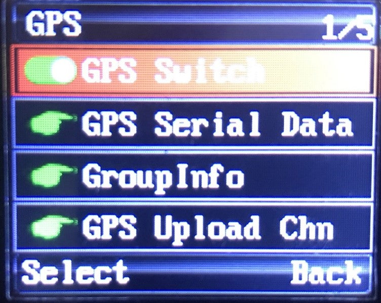
APRS_01.jpg

Enable GPS Switch.

Under GPS Serial Data tick all options.
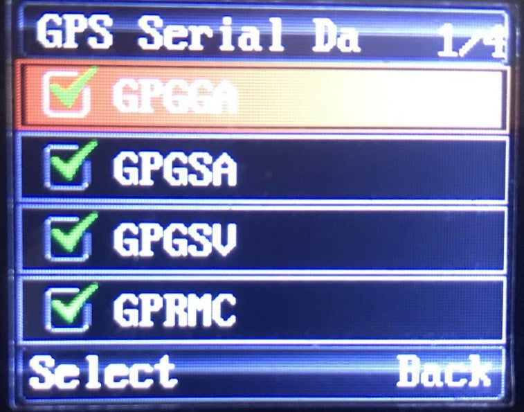
APRS_02.jpg

Go to Calibrator and set to AUTO.

Now go back to appendix menu and choose APRS.

In APRS Menu you have 5 options: APRS Type, Analog APRS, DMR APRS, Timer and Beacon.

APRS_03.jpg

Select APRS Type, you will see 4 options, select DMR+Analog APRS.

Under Analog APRS choose PTT Upload and choose TX End.

All other settings we will made in CPS.

1.3 Connect your Radio to your PC/Laptop

Connect your radio with USB cable and set proper USB Port by clicking on Comm Menu.

Choose proper COMM port and click Read, you will get response from your radio.

APRS_3.1.png

Always Read from the radio, do not open saved code plug.

1.4 DMR Service Menu

Go to the DMR Service and set:

GPS to ON, GPS Interval 10s, GPS Channel OFF

APRS_04.png

1.5 APRS Menu

Under the MENU APRS you have following:

APRS_05.png

1.5.1 Black frame settings:

Manual TX, set 15.

APRS Auto TX Interval set to 30s.

Under Beacon – set Beacon. Here you have two options – GPS Location or Fixed Location.

If you choose Fixed Location your radio will transmit GPS Coordinate marked in green frame!

1.5.2 Green frame settings:

You can find own coordinates by web browser or visit www.aprsdirect.com.

Be Aware that those Coordinate are in Slovenia right now.

Those are in format Latitude 46°10' 11ˇ N and Longitude 14°20'18ˇ E


1.5.3 RED frame settings:

TX frequency: for Europe Africa and Russia is 144.80, for all other counties check picture bellow.

TX QT/DTQ – this is analogue or digital tone. Leave this to OFF. If in your country is in use tone, that ask your local igate owner what kind of tone is
used to open igate.

Transmit Delay and Preware Time: Optimal setting are 500ms and 300 ms, if you think this scan be decreased, go ahead and test it.


1.5.4 BLUE frame settings:

YOUR SSID: you have options from 0 to -15, it up to you what kind of extension you would like to have. Usually 0, -1.-2 are used for fixed location, -7 for weather station, all other extension can be normally used.

APRS Signal Path: WIDE1-1, is working fine, you can also use WIDE2-1 and WIDE2-2. Always use this without any space.

You Call Sign: put in your call sign.

APRS Symbol table: there are two option according to APRS map chart – primary symbols ˇ/ ˇ and alternate symbols ˇ \ ˇ

Map Symbols can be found at this link: https://www.yachttrack.org/info_camper/downloads/APRS_Symbol_Chart.pdf

APRS Map Icon: According to the map symbols you can use whatever icon you like.

Your Sending Text: Here you can write a text, that everyone can be seen, if click on your call sing in web page www.aprs.fi or
www.aprsdirect.com

APRS_06.png

1.5.5 Yellow Frame Settings:

This setting are for digital APRS via DMR repeater’s.

Report Channel You can choose Current channel, or any other channel in your channel list. I recommend to use Current channel.

APRS TG: this is assembly from country code (293 for Slovenia) and 999 for TG for Brandmeister. 293999 is for Slovenia.

Report Slot: In Europe is allowed to transmit Digital APRS only on Time Slot 2.

Call Type: Digital APRS must be set to Private call.

PTT: options are OFF and ON. If you choose ON, that every time you released PTT button radio will transmit APRS.

APRS_07.png

2.0 Digital APRS registering at Brandmeister.

For Digital APRS you must be registered to Brendmaister. Please check what type of DMR repeaters are in use in your country.

Go to the following web page: https://brandmeister.network/

Klick register and filled up all necessary data. Sometimes you need to way a while that your account be to confirmed.

After confirmation click to Login and put in your credentials.

Click on your call sign on the right upper corner and choose Selfcare.

APRS_08.png

Brand: Choose Chinese radio.

Language: Choose your language on drop down menu.

APRS interval: choose 60s.

APRS Callsign: put your callsign and extension from -1 to -15.

APRS Text: put your text in, but MAX 12 letters!

APRS Icon: choose your Icon which will be displayed on web pages like aprs.fi and aprsdirect.

In Call GPS, Compact/CSBK data and Text Capture: leave to OFF.

AirSecurity/TOTP: OFF

Hotspot Security: if you have a hotspot, then put in your personal password.

Do not forget to press SAVE button at the end.

3.0 Channel setting in your code plug for analog APRS

For test make one analog channel and name it APRS ANA.

Put correct RX and TX frequency for your country. Check picture above.

ARPS_09.png

Move slider to the right and under APRS choose APRS(A) for this analog channel.

APRS_10.png

Column marked with RED - you can choose from OFF to 9 APRS(A) in drop down menu.

Row marked with Green is channel we made for test. You need to choose APRS (A).

As you can see you can choose analog APRS(A) on any channel!

WARNING: analog APRS will work only on analog channels!

4.0 Channels settings in code plug for Digital APRS

NOTE: in Europe digital APRS is allowed to transmit only on TS2!

ARPS_11.png

On your digital channel, set everything as normal talk channel, TX, RX frequency, Power, TX, RX Time Slot, TX, RX Colour Code… etc.

APRS_12.png

At the end of the row, on the right side, under the APRS column for TS 1 choose 2, and for TS2 choose 1 - that mean current channel.

APRS-13.png

Under APRS Menu you need to choose Report Channel, filled in proper APRS TG, you need to choose TS2, Private CALL and under PTT is option, when you released PTT button APRS will be sent.
Now press button WRITE that everything will be written to your radio and wait that radio reboot itself.

5.0 How to obtain GPS Lock on your radio

5.1 Option 1

You need to be in open spare/area and have visible look to sky. Turn on radio and wait that radio lock to the GPS satellites When Radio locked to the satellite you will observe green icon in the upper centre of the screen. If there is NO GPS lock icon is RED.

APRS_14.png

5.2 Option 2

You can buy a kit of two GPS antennas with SMA connector and connector for external power supply. One is receiver (install it outdoor) and second antenna is transmitter (install it indoor), connect external power supply and you have GPS signal in your room.

APRS_15.png

6.0 DISLACIMER

I’m NOT TAKING ANY RESPONCIBILLITY for any sort of damage or any sort of interferences you may make with your radio equipment.

Everything you do, you do it on your own risk, don’t blame me, if there will be some damage or not working. Read manuals again!

If you not familiar with DMR please take your time and search on web or ask any of your colleague what DMR is and how it works.

If you not know how to program your radio, then ask any of your friend how to do it.

WARNING: Firmware is not finish yet so Digital APRS will transmit and proper work only on TS2

DO NOT CHOOSE Digital APRS to work on TS1, because IT WILL NOT WORK and you will make an unnecessary traffic on TS1!

NOTE2: Digital APRS will work only on digital channels!

That guide is completely my project and its only lead you how to set up your radio to send Analog and Digital APRS.

We are working very hard to fix firmware in the near future that all function will be operational

Does It Have AES 256 Encryption As A Standard?

It's AES 128 standard.

Missing File Error When Installing The CPS

When trying to open the DB25-G CPS, you may encounter an error that a necessary file for the program to run is missing. Navigate to the folder where the application is located and right-click on the App: DB25_GMRS_CPS.exe Select Run as Administrator - Windows will now find the file in the same directory as the App and allow you to use CPS.

UV-5X
GT-3TP
DM-1701
Firmware Update
Cannot Receive Transmissions From Others, CTCSS/DCS Setting
How To Solve The Issue That The Radios Keep Monitoring NOAA Until They Receive A Transmission?
Can I Use GMRS in Canada?
Firmware Update

The Link Below will provide the firmware update application and new firmware, as well as the latest Programming Software build.
https://baofeng.s3.amazonaws.com/Baofeng_UV-5X_Firmware_V1.9_CPS_V2.0_Update_20210309.zip

Download, Extract and Open the UV-5X Firmware Update Folder

1_5b379495-4a7a-4f4b-9b58-4725cc3b1721.png

Open the BF_Download APP

2_d208246d-6ce0-4a5a-a51b-530dcd62f72f.png

3_95995731-4a24-4c85-96b1-947a50e0d01d.png

Open Device Manager to determine com port number and select it using the highlighted field in the Downloader App

4_b523de36-79a6-4062-ab49-c599c1324361.png


1. Plug the programming cable into the computer and radio.
2. Press and hold the MONI + CALL key, then turn the radio on. The screen should show a wide block in the middle
3. Click Download in the Downloader app, and wait for 100%.
4. Turn the radio off, remove the programming cable
5. Turn the radio back on and select Menu Option 40 and follow through to Reset the radio.

The CTCSS/DCS Tones should now be cleared and the Bandwidth corrected.
Hi ,

The Link Below will provide the firmware update application and new firmware, as well as the latest Programming Software build.
https://baofeng.s3.amazonaws.com/Baofeng_UV-5X_Firmware_V1.9_CPS_V2.0_Update_20210309.zip

Download, Extract and Open the UV-5X Firmware Update Folder

5_5a9cd9a6-13c4-412e-9779-b84b4a0a20df.png

6_791fdad1-0870-47d0-b038-67de0a6e27d2.png

7_8ab0acd5-e909-49d2-87ae-4577e1fa58ba.png

Open Device Manager to determine com port number and select it using the highlighted field in the Downloader App


8_53ce47d6-6371-4909-961f-0a4bc12523ab.png


1. Plug the programming cable into the computer and radio.
2. Press and hold the MONI + CALL key, then turn the radio on. The screen should show a wide block in the middle
3. Click Download in the Downloader app, and wait for 100%.
4. Turn the radio off, remove the programming cable
5. Turn the radio back on and select Menu Option 40 and follow through to Reset the radio.

The CTCSS/DCS Tones should now be cleared and the Bandwidth corrected.

Cannot Receive Transmissions From Others, CTCSS/DCS Setting

The radio is set to a tone of 67 Hz by default, in the first 7 channels. It has a DCS tone number D023N set on channels 8 through 14. The repeater pairs on channels 23 through 30 use a CTCSS Tone of 136.5 Hz.

All channels have either CTCSS or DCS tones set and will have to be edited with the programming software, or the information shares with others needing to communicate with you. If the other radios do not transit a matching tone, you will not hear them.
https://radioddity.s3.amazonaws.com/Baofeng%20UV-5X%EF%BC%88GMRS%EF%BC%89Programming%20Software_20210220.rar

The easiest workaround is to press and hold the Monitor button (below the PTT) when you see a transmission coming in, but the speaker is not unmuted.

How To Solve The Issue That The Radios Keep Monitoring NOAA Until They Receive A Transmission?

By default, all channels are selected in the Scan Add column. The NOAA channels can be set to OFF, and will not stop the scan operation.

Can I Use GMRS in Canada?

GMRS does require a license in the U.S., but not in Canada.

In Canada, hand-held GMRS radios up to 2 watts have been approved for use without a license since September 2004. Typically these are dual FRS and GMRS units, with fixed antennas, and operating at 2 watts on some GMRS channels and 0.5 watts on the FRS-only channels.

Mic Modulation Problem

Problem:Using gt-3tp im getting reports my modulation is very low, how do i turn up my mic volume??? I'm on 70 cms and meters away from repeater.

Answer:There's no way to adjust the GT-3TP's (and other Baofeng analog radios') modulation/transmission audio volume. It could be the radio's problem. Replacement suggested.

Power-on Password Required

If your DM-1701 radio suddently required a power-on password while he did not (remember) try to set any password for the radio, try the following solution.

Solution:
The instructions below should assist you in removing the password.
If the default password set by the Programming Software (CPS) ""00000000"" does not work, the situation can be reversed, but it is going to take a few steps.
 

DM1701_PASSWORD-01.png


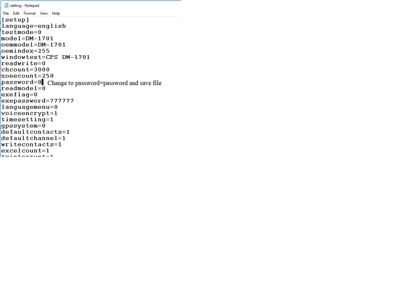
1). Using Windows File Manager, open the folder that the DM-1701 CPS is started from. The default location is C:\BAOFENG\CPS DM-1701 V1.0x, where x is the last digit of the Version. Located in this directory, you will find a file named ""setting"".

2). Open this file using Notepad (Right-Click on the File and Choose Open With, then Choose Notepad from the Application choices offered) .

3). Locate the Line that has ""password=0"". Change this to ""password=password"" & save the change. Save the edited file using the Save option, not the Save As option [See screen capture attached for setting file contents].

4). Then open the CPS (If already opened before editing the setting file, close the CPS and open it again for the CPS to recognize the change in the setting file) .

5). Write a Blank data file (codeplug) to the radio. This is generated with the New option from the File menu of the program software. It will contain the change in the setting file.
 
6). Once that is done, choose Read from the Program tab in the CPS to retrieve the modified codeplug.

7). Edit the data for the correct values - Password(s), Radio Name, etc. Items to pay attention to will be the Password and Lock in the Menu Item options & Power On Password in the General Setting options.

8). Write the corrected codeplug to the radio.


DM1701_PASSWORD-02.png

G90
GSOC
G1M
G90-H1
CE-19
X5105
X6100
Driver_FTDI Driver Used With The Xiegu Data Cable Not Working
Serial Driver For USB-cable Not Found
G90 Firmware Update
Can Not Power On After Failure of Firmware Update
Won't Power Off
No Signal
Some Keys Have No Backlight
For More Q&A
How To Operate The CAT Control & Digital Mode?
Xiegu USB Data Cable Driver Not Recognized By Windows
Driver_FTDI Driver Used With The Xiegu Data Cable Not Working

Some customers are finding that the FTDI driver in their Windows installation is now non-functional. This affects the Xiegu FTDI Data cable. It may affect other FTDI Cables as well.

The working driver to use instead of the non-functional driver in Windows can be found at the Future Technology Devices International (FTDI Manufacturer) website:

https://www.ftdichip.com/Drivers/CDM/CDM21228_Setup.zip

It is unknown why Microsoft has started to cripple its internal drivers. The one at the link above is functional.

It is the exact date and version as the now non-functional Windows driver that has been used for years.

When installing, it may prompt to replace existing files. Choose files based on matching dates and file sizes to replace the non-functional Windows driver.

Some customers may not have yet received the Windows update that cripples certain drivers.
 

Serial Driver For USB-cable Not Found

Check which type of driver circuit is built within your Xiegu-USB-communications cable. If it states FTDI, it is advised to use version 2.08.24 of the FTDI-driver. You find that driver on the FTDI website at: https://ftdichip.com/drivers/d2xx-drivers/

Make sure that you take version 2.08.24

G90 Firmware Update

1.. With the radio turned off --->> Open Device Manager
2.. Plug cable into the rear of radio (Labeled COMM) & computer USB Port (Or Side of Display is updating Display - Main Unit First)
3.. Observe Comport number in Device Manager
3a. Right Click USB Serial Port (Device manager), select Properties --->> Port Settings and confirm or select 115200 BPS
4.. Open the TeraTerm Folder
5.. Right Click on the ttermpro application
6.. Select Run as Administrator (Select Yes if prompted for permission to run the application)
7.. In the TeraTerm window, Click on Setup --->> Serial port (select or confirm port number) --->> Baudrate (select or confirm 115.2K)
8.. Click OK
9.. HOLD SPACEBAR DOWN
10.. Turn the radio on (If updating the Display, the Display will be Blank)
11.. Select 1 Update FW
12.. message - Erasing displays
13.. message - Wait for FW File (C will be in the TeraTerm Window)
14.. In TeraTerm window, Click on File --> Transfer --> XMODEM --> Send
15.. When the file window opens, navigate to the folder with the firmware files.
16.. Click on the Main Unit FW X.XX file (Or display, but do main first)
17.. Check the 1K Option
18.. Click on Open (If updating the Display, the Display will still be Blank)
19.. Firmware load starts
20.. When firmware load completes, disconnect the radio from the power source.
21.. Reconnect Power and turn the radio on.
22.. Confirm Version ( Hold Function and keep selecting next until opt 10 Version is displayed) Select Exit
23.. Follow the exact procedure for the display; data cable to display, select display firmware when prompted.
24.. Enjoy Radio!

For more detailed guide with images, CLICK HERE to check.

Can Not Power On After Failure of Firmware Update

The reason why this issue exists is that the firmware version of the front panel and the fuselage are inconsistent.

Xiegu recommends that you delete the file of the old firmware update package first, then click the Xiegu Download to download the latest firmware again.

The problem will be resolved after you upgrade the radio to the latest firmware. Please ensure both the front panel and the machine body has been upgraded to the same version.

Won't Power Off

Update firmware again with no antenna attached and Attenuator engaged.

OR

Perform the following:
1. Use the Function Button and the Lock Button to bring up the Scale adjustment
2. Advance it to level 4 or higher
3. Push Function again to toggle and check operation

If till can't fix it, pleaase tape a short video and send to us, we'll let our engineer take a look. Contact US

No Signal

Suggestion from Xiegu: The weak signal may be that the antenna system gain is not enough in the low frequency band, and our machine is nominally 1.8~30M for all amateur frequency bands. The receiving performance below 1.8M is not guaranteed to be as good as the amateur segment and the sensitivity of receiving AM broadcast is much lower. For SSB and CW, all of this kind of machines are like this. Suggest the customers try to receive local AM broadcasts, or re-flash the firmware.

Some Keys Have No Backlight

Some keys on the G90 actually have no backlights as they are designed. The light on some of the buttons is actually the light leaks from the LCD screen.

For More Q&A

We made a Xiegu G90 Q&A page for you. Hope it helps.

How To Operate The CAT Control & Digital Mode?


As you know, we not only sell radios, but also provide support to our customers. Often Xiegu G90 customers asked us about CAT control and digital mode operation with their G90. This was reason enough for our engineers to put together a document that includes all those bits and pieces required to successfully CAT control your Xiegu G90 and become active in digital modes such as FT8.


What can you learn from this document?

1. Explanation on vocabulary such as IO-port, CAT, CE-19 and OpenSource
2. How to connect your Xiegu G90 to your PC using the blue USB-cable
3. Easy CAT control using an OpenSource solution
4. required settings for PC and Xiegu G90
5. Xiegu G90 CI-V implementation
6. Details on some of the possible digital data modes
7. Software for CAT control and digital data modes
 

Download your personal copy at:

CLICK HERE to download the "Radioddity - Xiegu G90, CAT and Digital modes V1.0"


Xiegu USB Data Cable Driver Not Recognized By Windows

Many customers are reporting that the FTDI Drivers used with the Xiegu USB Data cable is no longer being recognized by Windows. For reasons unknown, Windows seems to be neutralizing some of the well-known drivers that are actually a part of the basic WIndows installation. Below is the manufacturer's site, info, and download link for the setup program to install a working driver.

Manufacturer's web site info:
https://www.ftdichip.com/Drivers/D2XX.htm

Direct download link:
https://www.ftdichip.com/Drivers/CDM/CDM21228_Setup.zip
 

How To Connect GSOC To PC via Bluetooth
Loose Knob
ALC Goes To 100% When Mic Keyed
How To Connect GSOC To PC via Bluetooth

Preparation:
GSOC does not have a built-in Bluetooth adapter, thus users need to prepare a USB Bluetooth adapter first. The recommended model is CSR8510 A10.

GSOC Settings:
Plug the USB Bluetooth adapter to any USB port of GSOC.
Click the connecting icon showing on the screen (the icon content is OFF LINE/G90 ONLINE/CAT ONLINE ) to pop up Bluetooth setting interface.

GSOC_Bluetooth_1.png

1. Turn on Bluetooth
2. Click SCAN to find the Bluetooth device list.
3. Click Connect/Disconnect button in the device list to connect/disconnect.
Note: For the first time connection, you need to allow the connection on you PC.

PC Setting:
Operating system Windows 10 x64, PC is with built-in Bluetooth.
1. Settings ->Bluetooth & other devices -> Turn on Bluetooth function

GSOC_Bluetooth_2.png

2. Settings ->Bluetooth & other devices -> More Bluetooth options

GSOC_Bluetooth_3.png

Check:
✔ Allow Bluetooth devices to find this PC
✔Alert me when a new Bluetooth device wants to connect

3. Click COM Ports

GSOC_Bluetooth_4.png

The GSOC BT ‘Serial Port’ is the correct port (COM8 in the image above).

Connecting Software:

At present Ham Radio Deluxe does not support Bluetooth port, we recommend you use flrig

1. Software Settings & Ports

Config->Setup->Transceiver

GSOC_Bluetooth_5.png

1.1 Set the data as the image above.

1.2 Click Init button to finish the Bluetooth connection.

Note: Due to uncertain factors such as the delay of the Bluetooth serial port, signal-to-noise ratio and other uncertain factors, occasionally unsuccessful situations may occur during the connection. At this time, just click the Init button to try again. If the error is still reported, please try closing flrig and repeat the above process

2. Connecting Interface

GSOC_Bluetooth_6.png


Loose Knob

We are very sorry to hear that the knob of your GSOC dropped off. However, that can easily be fixed by yourself. Gently squeeze the rubber ring surrounding the actual knob on its outer side and peel off that rubber ring. Be careful not to destroy it by using any sharp tools. You should be able to get it off just with your fingers You now see a hole underneath. Now with the rubber ring still off, reseat the knob on its corresponding axis. With a 2.5mm type Allen wrench and a few turns with a gentle push (just enough so that it does not fall off again), you should be able to refix that knob to its axis. Finally, reapply the rubber belt to the knob with its flat profile facing towards the knob and its teeth profile facing to the outside.

ALC Goes To 100% When Mic Keyed

The GSOC is more pronounced, the G90 just indicates 100%on the standard Display unit when the radio is keyed in SSB I believe it is more of an understanding of how the ALC works on the G90 than a problem in the radio. You can check for yourself. Install the display unit and set your G90 to SSB, key the mic, and look below the SWR bargraph. Instead of seeing the Bargraph on the GSOC go all the way to the right, the G90 head simply shows 100%.


In both cases, the ALC is displayed exactly the opposite of how our conventional radios work. The G90 needs an ALC of 95% to 100% as demonstrated by speaking into the mic at various mic gain levels. The hotter the audio, the less ALC.


RF Gain is another thing that takes some time to adjust to. The best signal to noise ranges are below 50% RF Gain; typically between 10% and 25%

About Radio Modes And TX Power
How To Update Xiegu G1M Firmware?
About Radio Modes And TX Power

Question:
Does the G1M radio suppot AM, SSB, CW, QRP?
Is the transmission power 2W in AM mode and 4W in SSB mode?

Answer:

The QRP is not a mode. Radios with a transmit power of less than 5W is called QRP. The G1M can work in USD, LSB, CW and AM modes.

CW is generally used to send Morse code (telegram). SBB is divided into upper and lower sidebands which are LSB and USB.

The transmission power of the G1M is 5W. Due to the difference in frequency bands, it will be higher or lower than 5W in some frequency bands. This is normal, and the power is regardless of the AM / SSB mode.

How To Update Xiegu G1M Firmware?

First of all, make sure you've got the latest firmware from Radioddity/Xiegu. CLICK HERE to download it.

It is possible that the firmware needs to be reloaded. This is most often seen when the radio is connected to a computer and turned on. I am including the firmware file

Open the link below, download and install the Teraterm terminal program v4.96

https://osdn.net/projects/ttssh2/releases/
 

Plug the USB Cable into the computer and open Device Manager. Click on the Com port, observe port number and set Port speed to 19200 BPS

Leave radio turned off

Open TeraTerm


Choose Setup, then Serial port

Verify com port number and confirm port speed is 115200 BPS

Hold the Space Bar and turn the radio on

Choose 1 to Update FW


Old FW is erased

When the FW is erased, You will be prompted for the new FW file

Choose File, Transfer, Send


Highlight the FW file, and put a checkmark in the Option for 1K. It will not load properly if this is not checked

Firmware transfer is started

On completion, you will be prompted to reboot your rig

Turn Radio off
REMOVE POWER CORD FROM RADIO AND COUNT TO 10
PLUG POWER CORD BACK IN
Turn on the Radio and the operation should be restored.


The Fan Runs All The Time

Please kindly note that 2650-3050 (R/min) is the maximum speed of this cooling fan. When your G90 is at about 25 degrees, the speed will be changed to about 200-300R /min. When at room temperature, the cooling fan will also rotate at a low speed. It is the design of this G90-H1 cooling fan, so it is normal that the fan runs all the time.

How To Connect the Xiegu CE-19 To The Radio And Computer?
CE-19 Computer Sound Card Interface - Straight Cable Method
How To Connect the Xiegu CE-19 To The Radio And Computer?

While it may be a more efficient way to operate soundcard modes using a dedicated interface connected directly to the radio and computer, the CE-19 has a purpose when the XPA125B amplifier is also used.

Using the CE-19 as the interface to connect to a computer for sound card modes can be achieved with the 3 patch cables that came with the interface.

CE-19 Computer Sound Card Interface - Straight Cable Method

The instructions below should help in building a cable to go from the CE-19 to your Computer Sound Card. For laptops and computers with sound cards dedicated to other purposes, an inexpensive USB sound dongle may be a good solution.

On the top of the CE-19 is the wiring legend for the AF connector.

The color code for the wires will be:
Black = GND (Ground)
Red = Center Ring (AF IN)
White = Tip (AF OUT)

With one cable designated as the one to go to the AF CON socket on the CE-19 (make an identifying mark), connect the black wires of all three cables together, solder and insulate. [CE-19 GND to computer Audio Input and Audio Output grounds]

Connect the White wire from the CE-19 cable to the red and white wires of the Cable designated as Computer Audio Input (Make an Identifying Mark) Solder and insulate. [CE-19 AF OUT Mono to Computer Audio In Stereo]

Connect the Red wire from the CE-19 cable to the red and white wires of the Cable designated as Computer Audio Output (Make an Identifying Mark) Solder and insulate. [CE-19 AF IN Mono to Computer Audio Out Stereo]

What we are doing is feeding the single CE-19 AF OUT (White) wire to the Left and Right terminals of the Computer Audio Input. We are feeding the single CE-19 AF IN (Red) wire to the Left and Right terminals of the Computer Audio Output. All 3 grounds are common to each other.

Use ferrites near both ends of each cable to reduce the chance of some of the RF distorting some of the digital signals.

If this cable is not capable of delivering stable Digital communications, consider a sound interface made for radio digital modes that have proper isolation and gain controls on the input and output. On this device, one end would plug into the G90 8 pin mini-din and the other to the computer USB port. All signals would be isolated.

If you are depending on the CE-19 for an RF Amplifier interface, the cable made from the instructions above may have to do.

We hope this makes the cable construction a little easier.

X5105 Firmware Update instructions
How To Use The Wi-Fi and Bluetooth Function?
For The Power Input Can You Clarify If The Center Pin Is Positive? Also, The Included Cable For Power Can You Also Clarify What Color Is Positive And Negative Polarity.
How Is CAT Control Achieved?
Please Confirm Touch Screen Capability.
Can the X6100 be left connected permanently to an external charger or external source of dc power with the charger turned off?
Can or should the X6100 be operated from an external power source with the charger turned off?
When should the charger be turned off?
When should the charger be turned on?
Does operating X6100 from an external power source with charger turned off affect the internal batteries of the X6100?
When operating the X6100 from an external power source to boost the output wattage should the charger be turned on or off?
How To Use The Wi-Fi and Bluetooth Function?

WIFI Operation Instructions

SCAN: Scan for nearby Wi-Fi / hotspots (Access Point)
CONNECT/DISCONNECT: Connect/disconnect the hotspot in the left list.
EDIT: Edit the element selected by the orange box on the right.
CONFIG: Move the orange box to the next.
EXIT: Exit the interface.
 

1. SYSTEM SETTINGWLAN – press MFK knob to enter the Wi-Fi setting interface

 ➟  ➟


2. Select a Wi-Fi to connect by rotating MFK – press CONFIG

 ➟


3. Press CONFIG to move to password – press EDIT to pop up the digital keyboard

 ➟
 

4. Enter/delete password by rotating & press MFK knob


5. Click ENTER by rotating & press MFK knob to confirm password (important)


6. Press EDIT to exit the digital keyboard


7. Press CONNECT, please wait for about 10s


8. WiFi connected!


9. Press EXIT to exit the Wi-Fi interface


10. Wi-Fi connected confirmed!


--- --- --- --- --- --- --- --- --- ---
 

Bluetooth Operation Instructions


OFF/ON: Turn on/off the built-in Bluetooth function.
CONNECT/DISCONNECT: Connect/disconnect the selected Bluetooth device on the left.
EXIT: Exit the interface.
Note: When the built-in Bluetooth function is displayed as "ON", it will always scan the surrounding Bluetooth devices.
 

1. SYSTEM SETTINGBLUETOOTH – press MFK knob to enter the Bluetooth setting interface
(for the first time, it should take about 1 minute to scan Bluetooth device, please be patient; will be 5s only from second time.)

 ➟  ➟

2. Select a Bluetooth device by rotating MFK – press CONNECT to connect
(please make sure your Bluetooth device is on)

 ➟

3. Bluetooth connected!

4. Press EXIT to exit the Bluetooth interface


For The Power Input Can You Clarify If The Center Pin Is Positive? Also, The Included Cable For Power Can You Also Clarify What Color Is Positive And Negative Polarity.

The center pin is positive. As for the included power cable, the white one is positive and black is negative.

How Is CAT Control Achieved?

CAT control via a USB-C cable.

Please Confirm Touch Screen Capability.

It doesn't come with a touch screen, but a color screen.

Can the X6100 be left connected permanently to an external charger or external source of dc power with the charger turned off?
Yes, it can be left connected. The Green LED will show activity if the Charger has not been toggled Off in the Radio Setting1 Menu.
Can or should the X6100 be operated from an external power source with the charger turned off?
Yes, as long as the Charger is toggled off in the Radio Setting 1 Menu, there is no problem running from an external power source. (13.8 VDC @ 3.4 Amps or above current capacity). The radio will operate from 9 to 15 VDC with current capacity requirements increased at a lower voltage than 13.8 VDC and reduced above 13.8VDC up to 15 VDC.
When should the charger be turned off?
The Charger should be used with the radio powered off. The Battery Management System (BMS) will start with a constant current charge that is indicated by a flashing Green LED. When the current demand from the battery tapers down to a steady low current set point, the charge state shifts to Constant Voltage for the 'finishing charge'. During this charging state, the Green LED will glow constantly. It is during this charging state that the 2 cells should be balanced-charged to their maximum of 4.2 VDC. The LED (in theory) should turn off when this state is completed, but there may be a conflict between the actual indicator of the completed charge and the LED Staying on to remind that the charger is still connected. I would recommend charging overnight, then toggling the charger back off in the System Setting1 Menu.
When should the charger be turned on?
The BMS will monitor battery capacity and voltage. It has voltage set points to first disable transmit capability and a 2nd set point to power the radio down to prevent the battery from being discharged below the point it can properly accept a charge. At this point, the charger should be enabled. During the first 4 charge /discharge cycles, you should charge fully and let the radio discharge the battery until the BMS shuts it down. After that, the battery has been 'built' to its rated current capacity and is more tolerant to partial charge cycles to top off a charge before the radio BMS shuts it down. The battery has a projected set number of charge/discharge cycles, so partial charging should be avoided if possible.
Does operating X6100 from an external power source with charger turned off affect the internal batteries of the X6100?
There should be no effect on the battery when the charger is off as indicated by the lack of the Green LED activity. I have not tried to generate a test setup to check for any current draw in milliamps or microamps to confirm this. There is no heat felt when the charger is off, and the radio remains connected to an external power source.
When operating the X6100 from an external power source to boost the output wattage should the charger be turned on or off?
The Charger should always be turned off when the radio is being operated; even for receive only. When the battery is under load, the BMS cannot sense a reduction in current demand. If used un-squelched, or for transmitting, the BMS only senses a rise in the current demand. This can cause excessive heat when the heat from the Power Amplifier (PA) components internal to the radio is combined with heat from the BMS circuit / Battery pack combination. The radio uses Passive Cooling (no cooling fan). The surface area of the outer case can dissipate heat from normal operations. Constant, or near constant carrier modes like FT8 (or other digital sound card modes), as well as CW and RTTY, place a higher demand on the PA section of the radio. The by-product is heating. Add the additional heat build-up from the charger circuit and the heat can become excessive. Combine this further with working in direct or near direct sunlight and the radio may shut down.
TH-9800
Unlock Frequency Range

In order to meet the FCC policies, the frequency ranges of the TYT TH-9800 radios we sell are locked in 28-29.7Mhz, 50-54Mhz, 144-148MHz and 420-450MHz. But users can unlock the frequency range if needed.

Here's the operation on how the unlock the frequency ranges:

1. Open the programming software
http://s3.amazonaws.com/s3.image.ro/download/TYT%20TH-9800_Programming%20SoftWare.zip

2. Connect the TH-9800 radio to the computer and load(''read'') it to the software

3. Press the Ctrl and the F11 key at the same time; then enter the password ""9800TYT''

(Note: On some Laptop Computers, the F11 Key may require the Function (FN) key to be used with the Ctrl key. If you have 3 commands available on the upper row of keys, yours may require the key with the same color as the F11 to be used with the CTRL and F11 keys)

4. Select Frequency Range from the Edit Tab.

5. Edit the frequency range
Maximum Frequency Range:
- 26-33MHz (RX/TX) (AM band RX)
- 47-54MHz (RX/TX) (AM band RX)
- 136-174MHz (RX/TX)
- 400-480MHz (RX/TX)

6. Write to the radio, turn off the radio and then turn on it again. Now, it can work in the expected frequency range.

Programming Cable
Driver Installation-Analog
Driver Installation-Digital
Driver Installation-Analog

If you failed to connect with the computer/software, please suggest him the followings.

1. Open the device manager

2. Plug in the programming cable to the computer

3. If you see there's a new device show up without a yellow warning sign, that means you have installed the driver well and you can start to connect the radio to the programming software directly.

If you see there's a new unknown device show up (with a yellow warning mark) after the cable is plugged in, uninstall it and then plug out the cable.

If there's no change or device show up after the cable is plugged in, there are two possibilities, one is that you have not installed a driver yet, the other is that the programming cable is defective or the cable does not make a good connection with your computer.

4. After unplugging the cable, install a new driver:

28-020-531 (Driver for Radioddity RD-201 programming cable):
https://rd-201-cable.s3.amazonaws.com/Radioddity%20RD-201%20Cable%20Drive.rar

28-020-122 (Driver for cable SKU 28-020-122):
https://manualsoftware.s3.amazonaws.com/Installation%20Guideline%20of%20Baofeng%20Programming%20Cable%20Driver.zip

5. Replug in the programming cable and see if there's a driver installed successfully. If yes, you can try to connect the radio and program it on the software.

If you are using the official programming software we provided, please make sure you select the correct com port on the software before you read from the radio.

If the radio still fails again to be programmed, please kindly take some screenshots of the error your computer shows and your device manager with the Other Devices opened when the cable is plugged in.   

Driver Installation-Digital

The radio's programming cable actually will install the driver automatically when you plug it in your computer the first time. However, sometimes the driver could go wrong and with the bad driver, the radio cannot connect to the computer.

Here's the instruction to check and get the driver installed correctly:
1. Open the device manager.

2. Turn on the radio.

3. Plug in the programming cable firmly to the radio (first) and the computer (after the radio).

4. If you see there's a new unknown device show up in the device manager (with a yellow warning sign) after the cable is plugged in, right click and uninstall it--plug out the cable from the computer (do not plug out the end which is connected to the radio and do not turn off the radio).

If there鈥檚 no changes or differences in the device manager after you plug in the cable, then the cable may be defective.

5. Replug the programming cable into the computer.

6. If there's a driver installation notice at the lower right corner, please just click ''skip from Windows update''.

7. Wait for 1-3 minutes and you can try to read the radio on the software

If the issue still exists, please feel free to let us know. We will offer you further assistance with our best.

\

Other Tips
What's Codeplug And How To Get It?
Where To Find Manuals, Software And Other Information Of Added Value?
How To Get On Air With My DMR Radio?
What is CTCSS and DCS?
What's Codeplug And How To Get It?

A codeplug is the programming data of your radio, you can get it from the programming software following the steps below:
1. Open the software, connect your radio to the software and read(download) from the radio
2. Click the first button ''Open/File'' on the top line, save and then the software will let you save the programming data and settings as a file. That file is the codeplug.

Where To Find Manuals, Software And Other Information Of Added Value?

For all customers of Radioddity we do offer all kinds of information and software free of charge. Just get on our website www.radioddity.com

Where_to_find_manuals_1.png

In the upper right click on "Support".

Where_to_find_manuals_2.png


Next select the brand of your radio (Radioddity, BAOFENG, TYT. XIEGU, OTHERS)

You will then be presented with a list of radios and accessories (of the selected brand) that we do offer additional materials for, such as manuals (often in other languages as well), CPS software, software for updating the radio, firmware and other kind of special material.

How To Get On Air With My DMR Radio?

Based on our customers questions and the feedback we got, our engineers created a very detailed document targeted at beginners with digital DMR-radios. The document takes your hand and accompanies you from the application of your personal DMR ID up to the creation of the required codeplug. Sample codeplugs for our DMR-radios are included as well.
 

What can you learn from this document?
1. Intention of this document
2. Make yourself familiar with DMR
3. Apply for and receive your DMR ID
4. Gather information about a DMR station
5. Install any USB-driver that might be required
6. Install CPS according to your DMR-capable radio
7. General process of creating a DMR code plug from scratch
8. Sample codeplugs


Download your personal copy at:

CLICK HERE to download the "Radioddity - Getting On Air With Your DMR Radio"
CLICK HERE to download the "Sample Codeplugs" (GD-77, RD-5R, DM-1701, GD-73, MD-9600)

What is CTCSS and DCS?

CTCSS: Continuous Tone Controlled Squelch System
DCS: Digitally Controlled Squelch

Cobra calls both of these features "Privacy Codes".
Privacy Codes are not extra channels -- rather they are a means for sharing a channel with other people without any annoying interference or cross talk. Even though there may be other people using the channel, you will only hear transmissions from those people who are using the same Privacy Code as you.

Radio Comparison
GA-2S VS R2
DB25 VS QB25
GT-3WP VS UV-9R Plus
GA-2S VS R2

Common:
2W, 16 channels, no screen, USB charger, support Chirp

Difference:
GA-2S:
USB charging without charger base available;
16 scanning channels;
Turn on/off VOX manually;
Side buttons can be defined as a scanning switch;
Acoustic tube earpiece;
UBS charging cable;
1500mAh Battery

R2:
Scramble function
1100mAh Battery

DB25 VS QB25

QB25:
quad-watch, quad-montor, quad-display, quad-band

DB25:
dual-watch, dual-monitor, dual-display, dual-band

P.S.
DB=DUAL-BAND, QB=QUAD-BAND

GT-3WP VS UV-9R Plus

The GT-3WP actually is the same model as the UV-9R, but sold by different distributors so the model name is different. The UV-9R Plus is an 8W UV-9R.

EUR